|
1.1 Pantograph
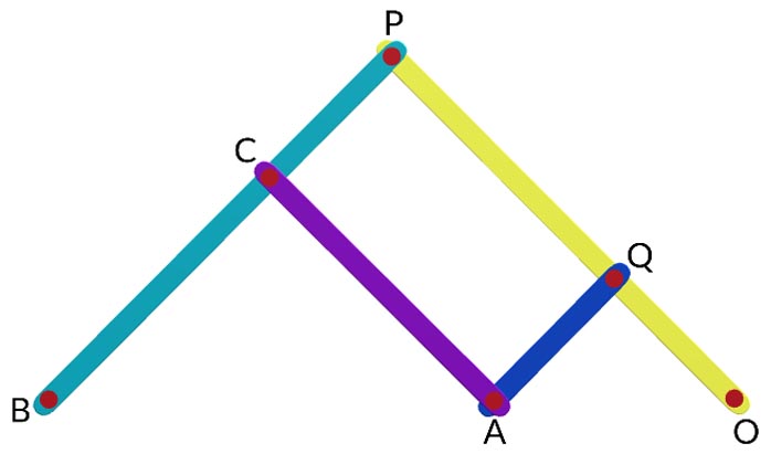
It is some time necessary to reproduce to an enlarged scale or a reduced scale and as exactly as possible the path described by a given point. A pantograph is a mechanism which is used for this purpose. The links are pin jointed at A, B, C, D such that AB II CD and BC II AD.
The point P will reproduce the motion of the point Q at an enlarged scale or alternately the point Q will reproduce the motion of the point P to a reduced scale. From similar triangle OBP and OAQ.
OQOP=OAOB
The displacement of Q is therefore parallel to the displacement of P and is smaller than that of P in the proportion OA x OB. The pantograph is used to trace the displacement of the crosshead or piston of a reciprocating engine.
|
|
1.2 Straight line Motion Mechanism
Exact Straight Line motion Mechanism: It is frequently necessary to constrain a point in a mechanism to move along a straight path. But sliding pairs are not used for this purpose as it is bulky and are subjected to rapid wear. Turning pairs are preferred.
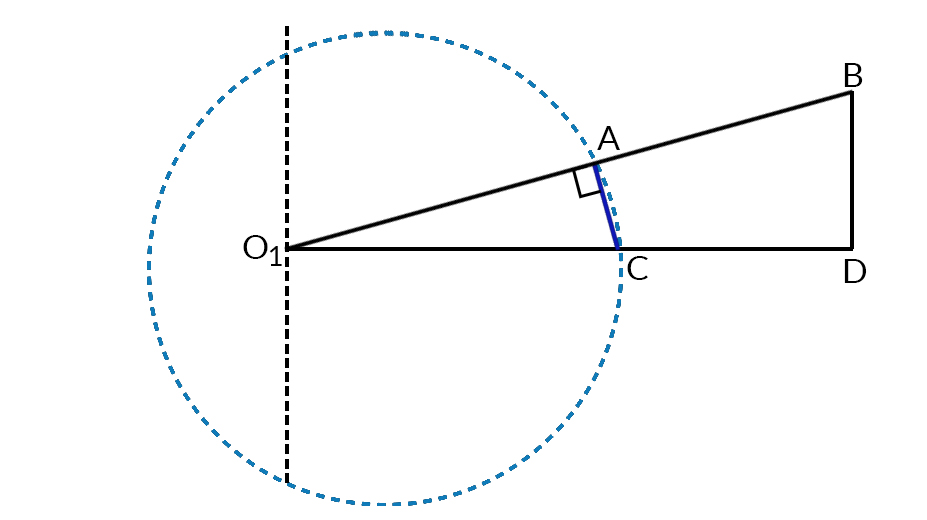
Condition for exact straight line motion: OQP be the three distinct point of a mechanism. If OP X OQ = Constant. , then the path of P will be a straight line perpendicular to the diameter OR of the circle along the circumference of which Q moves.
OQR and OPX are similar triangle.
OQOX=QRPX=OROPOX=OQ.OPOR
In the above expression OR is constant. If OQ x OP is const, then OX will also be constant.
|
|
1.2.1 Paucellier Mechanism
It consists of eight links. The pin Q is constrained to move along the circumference of a circle of diameter OR by the link QA which acts as a driver. The crank QA and fixed link OA are equal. The pin P and Q are at opposite corners of a four-bar chain with all links are equal in length. Link BO and CO are of equal length.
Link QB = PC and OB = OC
In triangle OBF and BPF
OB2=OF2+BF2
BP2=PF2+BF2
OB2−BP2=OF2−PF2
=((OF+PF)(OF−PF)=OP:OQ
But,
OB2–BP2 = Const. - - - - - - - - - since OB & BP are const.
Thus,
OP.OQ is constant and P traces out a straight path perpendicular to OA
|
|
1.2.2 Hart Mechanism
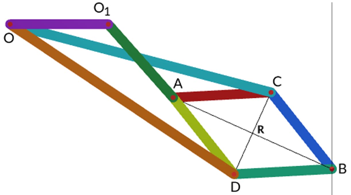
Hart mechanism consists of six links such that CF = ED; CD = FE and OO1 = O1A. The four link FC, CD, DE and EF form a crossed parallelogram. The line joining B & D and C & E will be parallel for all positions of the links. OO1 is the fixed link which is equal to the rotating link O1A.
The three points O, A and B lie on a straight line parallel to FD or CE for all positions of the mechanism in such a way that the product OB.OA remains constant for all positions of the mechanism.
In the triangle EDF
FE2=FD2+DE2−2FD.DE.Cos(<BDE)
also,
Cos(<FDE)=(FD−CE)2.DE,
Thus
FE2=FD2+DE2−2FD.DE.(FD−CE)2.DE
FD:CE=FE2−DE2= constant as the link FE and DE are constant.
Also, FCD and OCA are similar triangles, therefore,
FD FC=OA OCor,FD=OA.FC OC.........(i)
and, CFE and OFB are similar triangles, therefore,
CECF=OBOFor,CE=CF.OBCF........(ii)
From (i) and (ii)
FD.CE=(FC.OAOC)(FC.OBOF)=(FC2.OA.OBOC.OF)=constant
Since FC, OF, OC are constants, hence the product OA.OB will be constant. Thus the path traced by B will be a straight line.
|
|
1.2.3 Straight line Motion Mechanism with one sliding pair
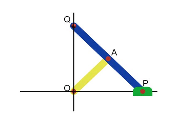
Scott-Russel Mechanism:
The mechanism is essentially the same as that of the reciprocating engine. Here the straight line is not generated but is merely copied. The crank OA is equal to the connecting rod AP. The connecting rod is extended to Q such that AQ = AO = AP. Q moves along a straight path normal to OP. This Straight line motion is not much practical use, since it makes use of a sliding pair. Friction and wear is higher.
|
|
1.3 Approximate Straight line Mechanism
|
|
1.3.1 Watt Mechanism
It is a four bar mechanism. It has four links OA, QB, AB and OQ. OQ is the fixed link. Links OA and QB can oscillate about centre O and Q respectively. It is observed that if P is a point on the link AB such that PA/PB =QB/OA, then for small oscillation of OA and QB, P will trace an approximately straight line.
Application of Watt's mechanism
Watt’s mechanism is used in the rear axle of some car suspensions as an improvement over the panhard rod. This mechanism is used to prevent sideways motion between axle and body of the car.
|
|
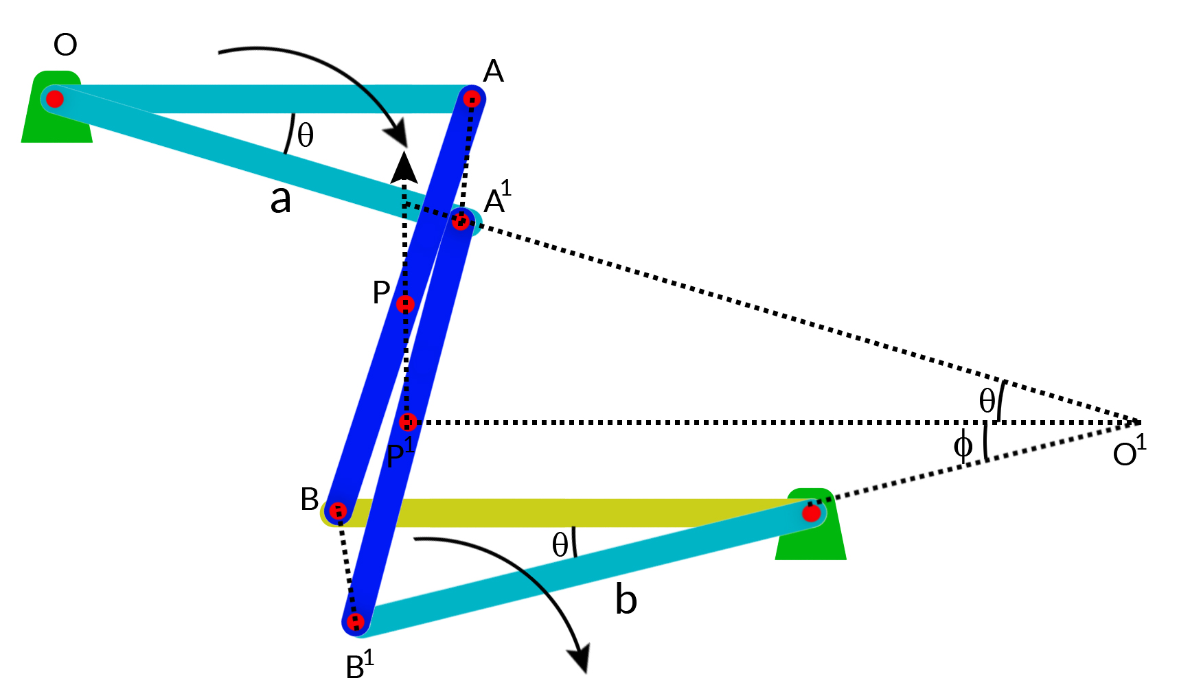
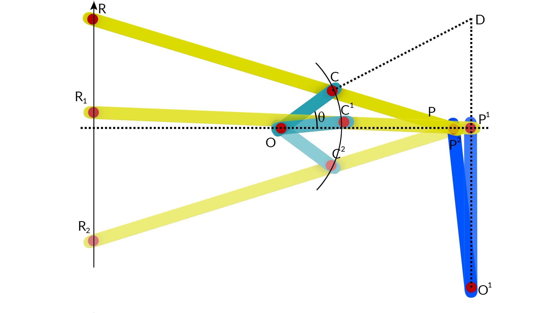
1.3.2 Grass-Hopper’s Mechanism
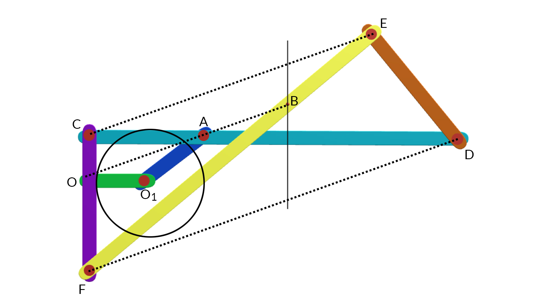
The mechanism is a derivation of the modified Scott-Russel Mechanism in which the sliding pair P is replaced by a turning pair. This is achieved by replacing the slider with a link O1P perpendicular at the mean position with turning pair at P and pin jointed at O1. The point R on the extension of the link PC describes an approximately straight path for smaller angular displacement of OC. In order to make R to describe an exact straight line, the point P moves in an approximately straight line perpendicular to O1P.
|
|
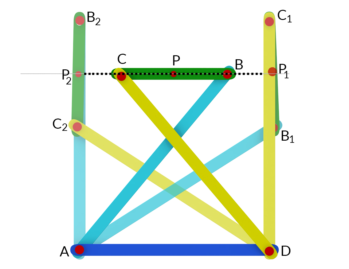
1.3.3 Tchebicheff Mechanism
It consists of four bar mechanism with crossed links AB and CD of equal length. The point P is situated at the midpoint of the link BC. The proportion of the links are taken in such a way that B, P and C lie on vertical lines when on extreme positions i.e., when directly above A or D.
|
|
1.3.4 Roberts mechanism
This is also a four bar mechanism which in its mean position has the form of a trapezium. The links AD and BC are of equal length and AB is fixed link. A bar EP is rigidly attached to the link CD at its midpoint E. If the mechanism is displaced the point P will trace an approximately straight line.
|
|
1.4 Steering Gear Mechanism
When a vehicle is moving along a curved path, the steering gear must be so designed that the paths of the points of contact of each wheel with the ground are concentric circular arcs. Steering is usually effected by turning the axes of rotation of the two front wheels relative to the chassis or the body of the vehicle. The wheel on the inside of the curve must be turned through a larger angle than the axis of the wheel on the outside of the curve. The condition of correct steering of all wheels in an automobile is to make them turn about a single instantaneous centre of rotation G.
AC = EF = EG – FG = AE Cotθ ϕ −CF Cot θ=AE(Cot ϕ−Cot θ)
(Cot ϕ−Cot θ)=ACAE=aL
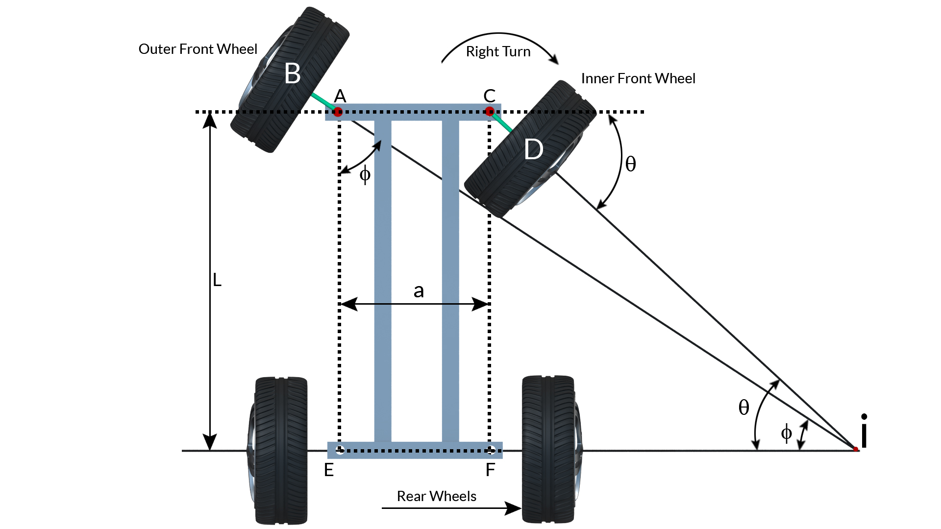
Fig 1.4 Steering gear mechanism
Thus a steering gear is a mechanism for automatically adjusting the value of θ, ϕ for correct steering. Two different steering mechanisms are as below:
|
|
1.4.1 Davis steering gear mechanism
The arms AK and CL are fixed the axles in such a way to form bell crank levers BAK and DCL with equal angles. The arms are slotted and slide relative to two die blocks which are pivoted to the link MN, the link MN is made to move parallel to AC at a distance h. Steering is effected by sliding MN either to the right or to the left. In the neutral position AK and CL are each inclined at an angle α to the centre line of the car. When the link MN is moved though a distance x to the right relative to the chassis, the bell crank levers are moved to the new positions and BA and CD when produced intersect at G.
Let φ and θ be the angles through which the arms AK and CL are turned.
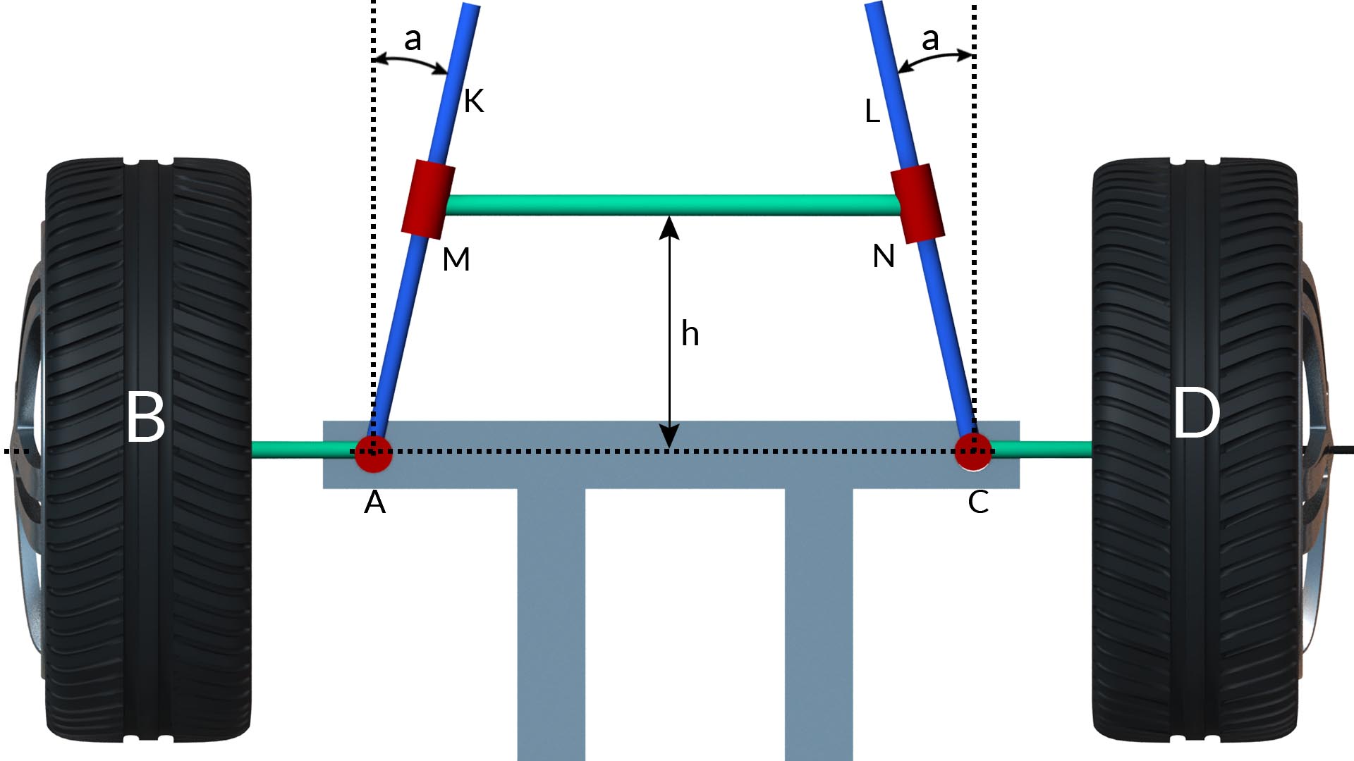
Let h = distance of MN from AC
2b = difference between AC and MN
tan α = b/h
tan(α+ϕ)=b+xhandtan(α−θ)=b−xh
tan(α+ϕ)=tanα+tanϕ1−tanα.tanϕ=b+xh
=bh+tanϕ1−bhtanϕ=b+xh
=b+h tanϕh−b tanϕ=b+xh
tanϕ=xhh2+b2+bx
tan (α−θ)=tanα−tanθ1+tanα.tanθ=b−xh
tan θ=xhh2+b2−bx
cotϕ−cotθ=h2+b2+bxxh−h2+b2−bxxh=2bh=2 tanα
Thus, condition for correct steering,
tanα=a2W
Disadvantage of Davis steering is that friction is high and wear at the contact surfaces rapidly impairs the accuracy of the mechanism.
|
|
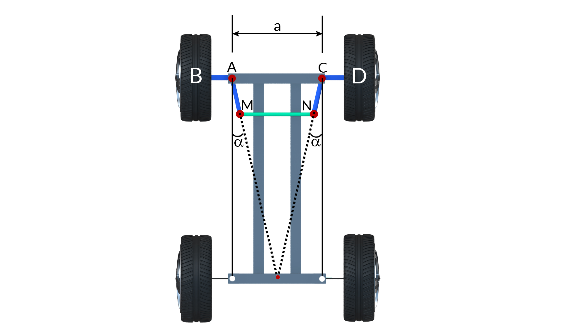
1.4.2 Ackermann Steering Gear Mechanism
It consists of turning pairs and is based on a four bar chain in which the two longer links AC and MN are unequal in length while the two shorter links AM and CN are equal in length. In the mid position when the car is moving along a straight path, link AM and CN makes an angle α to the longitudinal axis of the car. It can be seen that Cotϕ.Cotθ=ACQP. This is obviously not a constant for all steering positions and therefore cannot satisfy the condition for correct steering. The advantage of this linkage is that it has no sliding pairs and therefore easy to maintain without much wear. The best possible steering is found when the point J from AC is about 0.7 times the wheel base.
|
|
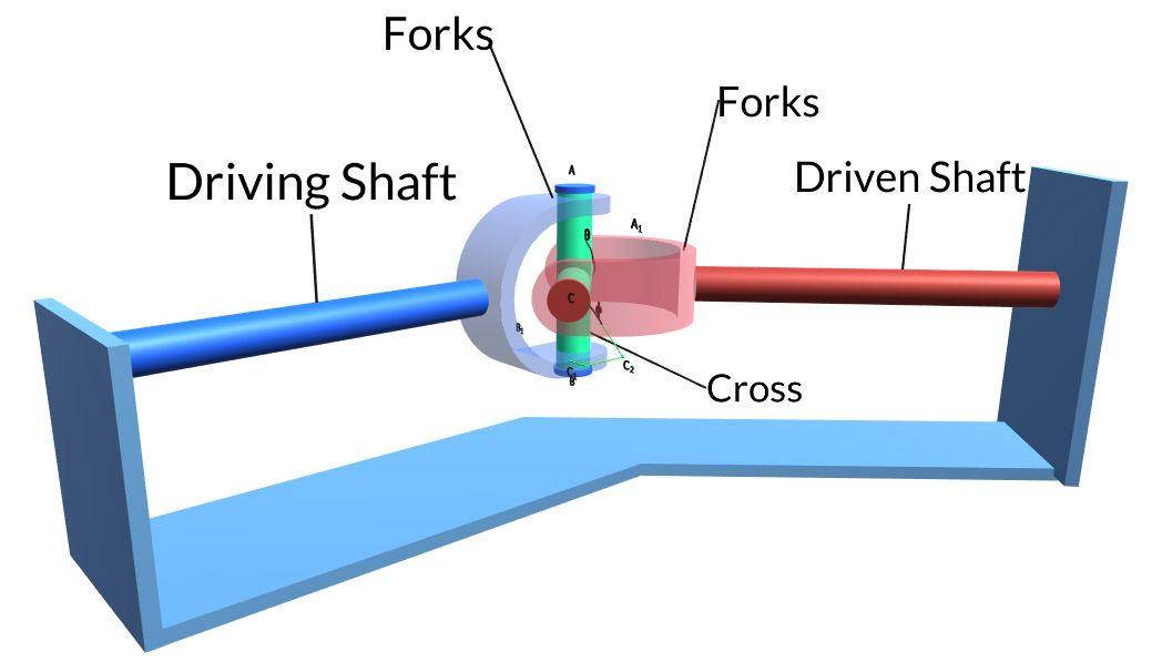
1.5 Hooke’s Joint
Hooke’s joint is a positive mechanical joint used for connecting shafts, whose axes are inclined at an angle to each other. It is also known as universal coupling, U-joint, Cardan Joint. It compensates angular misalignment between the shafts in any direction. It is used for transmitting power from engine gear box to the rear axle of the automobile. The angle between the driving and the driven shafts may be constant, but usually it varies while the vehicle moves on uneven surface. One of the disadvantages of this joint is that the velocity ratio is not constant because the driving shaft rotates at a uniform angular speed but the driven shaft rotates at varying angular speed. Because of this single Hooke’s joint is not recommended for high speed systems.
|
|
1.5.1 Application of Hooke’s Joint
Hooke’s joint has a wide range of applications. It is used in:
- Driveshaft
- Automobile propeller shafts
- Stone crushers
- Centrifugal blowers
- Centrifugal fans and centrifugal pumps
- Belt conveyors
- Control mechanisms
- Marine equipments
- Metal forming machinery
- Sockets
|