Gyroscope

1.1 Gyroscope

Gyroscope is a mechanical system or arrangement which is generally employed for the study of precessional motion of a rotary body. It is derived from the word ‘Gyre’, a Greek word, meaning circular motion it finds its applications in gyrocompasses, aircraft, naval ship, control system of missiles and space shuttle. Very carefully engineered gyroscopes are used for navigation because the axis of spin point in a nearly fixed direction when external torques are small. This makes the gyroscope a good replacement for a magnetic compass, particularly in regions where magnetic compasses are unreliable.

A gyroscope consists of a rotor mounted in the inner gimbal which is mounted on a fixed frame as shown in Figure. When the rotor spins about X-axis with angular velocity ω rad/sec and the inner gimbal precesses about Y-axis, the mechanism is forced to turn about Z-axis other than its own axis of rotation and the gyroscopic effect is thus setup. The resistance to this motion is called gyroscopic effect.
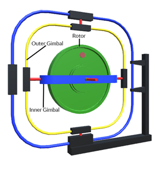
Gyroscope


The three mutually perpendicular axes are called

(i) Axis of spin along X-axis.
(ii) Axis of precession along Y-axis.
(iii) Axis of gyro-couple along Z-axis.

There are three mutually perpendicular planes as shown in Figure called

(i) Plane of spinning in YOZ plane perpendicular to X-axis
(ii) Plane of precession in XOZ plane perpendicular to Y-axis
(iii) Plane of gyro-couple in XOY plane perpendicular to Z-axis

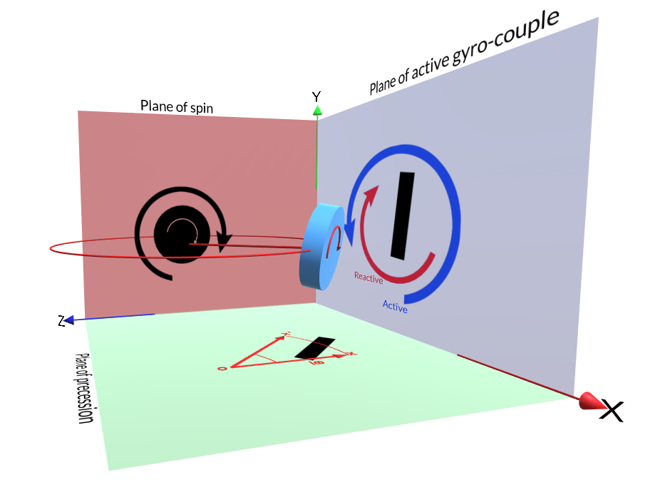
Three Mutually Perpendicular Planes

Three mutually perpendicular planes (Fig.- 10.2)


Let a disc of moment of inertia I, rotate at an angular velocity ω rad/sec about the X-axis. Let the disc spins about X-axis called the spin axis, the angular momentum of the rotating disc is given by Iω. Now suppose the spin axis precesses through a small angle δθ about Y-axis in the plane XOZ, with an angular velocity of ωp rad/sec.

Let the vector OX shown in Figure, represents the angular momentum of the disc, Iω. Let it changes to OX’ by a small angle δθ in a time interval of time δt in the XOZ plane.

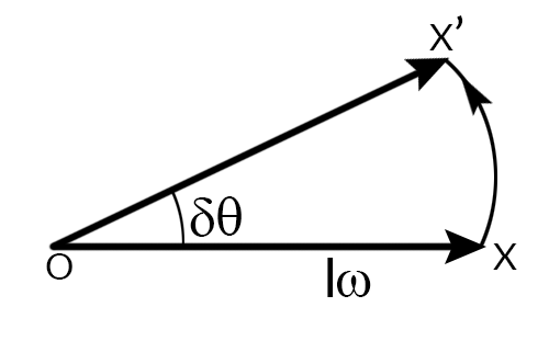
Angular momentum vector (Fig.- 10.3)


The change of angular momentum,

XX=OX.δθ=Iωδθ

and the rate of change of angular momentum

=Iωδθδt

This rate of change of angular momentum will give rise to a couple to the axis.

C=limδθ 0(Iωδθδt)=Iωdθ dt=Iωωp,where ωp is the angular velocity of precession.

The gyroscopic couple is given by C = I.ω.ωp where ω.ωp is the acceleration components. The direction of torque vector will be along the spin vector on rotating spin vector in the direction of precession vector. To cause precession of a spinning body, an external torque must be applied to the body or a rotor in a plane normal to the plane in which the spin axis is precessing.

Direction of Spin vector, Precession Vector and Couple Vector with Forced Precession

To determine the direction of spin, precession and couple vector, right hand screw rule or right hand rule is used.

Right hand rule: Let the four fingers of the right hand represent the rotation, then the thumb shows the direction of the spin vector. The precession vector direction is also found in the same manner.

Rotate the spin vector in the direction of precession by 90o, in order to get the direction of the gyro-couple. Please note that, for analyzing the gyroscopic effect of the body, always reactive gyroscopic couple is considered.

1.2 Gyroscopic action on aeroplane

Aero planes are subjected to gyroscopic effect when it taking off, landing or negotiating left or right turn in the air.

Let,
    ω = angular velocity of the propeller in rad/sec.
    M = mass of the engine propeller in kg.
    k = radius of gyration in m.
    I = mass moment of inertia of the engine/propeller = Mk2
   V = speed or linear velocity of the aero plane in m/sec.
    R = radius of curvature in, m.
    ωp = angular velocity of precession = VR
Gyroscopic couple acting on the aero plane, C=Iωωp

Let us analyze the effect of gyroscopic couple acting on the body of the aero plane for various conditions.

Case I: When the aero plane engine or propeller rotates clockwise when viewed from the rear and the plane turns towards left

Gyroscopic Action on Aeroplane

Gyroscopeic Action (Fig.- 10.4)


The effect of the reactive gyroscopic couple is to raise the nose upwards and dip the tail downward.

Case II: When the aero plane engine or propeller rotates clockwise when viewed from the rear and the plane turns towards right.

The effect of reactive gyroscopic couple is to dip the nose downwards and raise the tail upwards.

Case III: When the aero plane engine or propeller rotates anticlockwise when viewed from the rear and the plane turns towards left

Gyroscopic Action on Aeroplane

The effect of the reactive gyroscopic couple is to lower the nose downwards and raise the tail upwards.

Case IV: When the aero plane engine or propeller rotates anticlockwise when viewed from the rear and the plane turns towards right.

The effect of the reactive gyroscopic couple is to raise the nose upwards and lower the tail downwards.

1.3 Gyroscopic Action On Ship:

Gyroscope is used to stabilization and directional control of a ship sailing in the rough sea. A ship while navigating in the rough sea may experience the following three different types of motion.

(i) Steering :- Ship taking a turn towards left or right while moving forward.
(ii) Pitching :- Ship oscillating in a vertical plane along a horizontal axis and about the transverse axis clockwise or anticlockwise.
(iii) Rolling :- Sideway motion of the ship about longitudinal axis.

For stabilization of a ship against any of the above motion, the major requirement is that the gyroscope shall be made to precess in such a way that the reaction couple exerted by the rotor opposes the disturbing couple which may act on the frame.

The top and front views of the ship are shown. The following are some special terms used in ships.

(i) Bow (fore-end): The front side of the ship is called bow.
(ii) Stern or aft (rear-end): The back side of the ship is called stern or aft.
(iii) Port: Left portion of the ship when viewed from the back is called port.
(iv) Starboard: Right portion of the ship when viewed from the back is called starboard.

Gyroscopic Action on Ship


 1.3.1 Effect of Gyroscopic Couple on the Ship During Steering:

When the rotor of the ship rotates in the clockwise direction when viewed from the stern, it will have its angular momentum vector in the direction OX.

As the ship steers to the left, the active gyroscopic couple will change the angular momentum vector from OX to OX’. The vector XX’ now represents the active gyroscopic couple and is perpendicular to OX.

The effect of this reactive gyroscopic couple is to raise the bow and lower the stern.

Effect of Gyroscopic Couple on the Ship During Steering


When the ship steers to the right under similar conditions the effect of reactive gyroscopic couple is to lower the bow and raise the stern.

 1.3.2 Effect of Gyroscopic Couple on the Ship During Pitching:

Pitching is the movement of a ship up and down in a vertical plane about transverse axis with SHM. In this case the transverse axis is the axis of precession.

 1.3.3 Pitching types and their effect:

i) When the pitching is upwards: The effect of reactive gyroscopic couple will be to move the ship towards starboard.
ii) When the pitching is downwards: The effect of reactive gyroscopic couple is to turn the ship towards port side.

 1.3.4 Effect of Gyroscopic Couple on the Ship During Rolling:

For the effect of gyro-couple to occur, the axes of precession should always be perpendicular to the axis of spin. But in case of rolling of a ship, the axis of precession is always parallel to the axis of spin for all positions. Hence there is no effect of the gyroscopic couple acting on the body of a ship.

1.4 Stability Of Two-Wheeler:

A two wheeler vehicle taking a turn over a curved path. The vehicle is inclined to the vertical for equilibrium by an angle θ known as angle of heel.

Let,
    M = mass of the vehicle and rider in kg
    W=Mg, Weight in Newton
    h= Height of the centre of gravity of the vehicle and rider in m.
    Rw = Radius of the wheel in m.
    Iw = Mass moment of inertia of each wheel.
    Ie = Mass moment of inertia of the rotating parts of the engine.
    R = Radius of the track in m.
    ωw = angular velocity of the wheel in rad/sec
    ωe = angular velocity of the rotating parts of the engine in rad/sec
    G = gear ratio = ωeωw
    V = linear velocity of the vehicle = ωw.Rw
    ωp = angular velocity of precession in rad/sec = VR
   θ = Angle of heel.

STABILITY OF TWO-WHEELER


 1.4.1 Effect of Gyroscopic Couple:

V=ωw.RwandG=ωeωw, therefore ωe=G.ωw=GVRw

Angular momentum due to wheels = 2.Iw.ωw

Angular momentum due to engine = Iw.ωw=Iw.GVRw

Thus total angular momentum=Iω=2Iw.ωw±IwGVRw=>2.Iw.VRw±IwGVRw=>VRw[2.Iw±IwG]

Since the axis of spin is inclined to the horizontal at an angle θ. Thus the total angular momentum vector due to spin is represented by OX’ inclined to OX at an angle θ. But the precession axis is in vertical direction. Therefore, the spin vector is resolved along OX.

Gyroscopiccouple:Cgyro=IωωpCosθ=>Cgyro=VRw[2.Iw±IwG]CosθVR

When the engine is rotating in the same direction as that of the wheel, then the (+) sign is used. (-) sign is used if the engine rotates in opposite direction.

Effect of gyroscope couple (Fig.- 10.9)

The gyroscopic couple will act over the vehicle outwards i.e., in the anticlockwise direction when seen from the front of the two wheeler. This couple tends to overturn /topple the vehicle in the outward direction.

 1.4.2 Effect of Centrifugal Couple:

Centrifugal force;Fc=MV2R

Centrifugal Couple; Ccentri=Fc.hCosθ=(MV2R)h.Cosθ

The centrifugal couple will act over the two wheeler outwards, i.e., in the anticlockwise direction when seen from the front of the two wheeler. This couple tends to overturn/topple the vehicle in the outward direction.

Total overturning couple; C=Cgyro+Ccentri =>VRw[2.Iw±IwG]CosθVR+(MV2R)h.Cosθ

For the vehicle to be in equilibrium, overturning couple should be equal to balancing couple acting in the clockwise direction due to the weight of the vehicle and rider.

Balancing Couple;C=MghSinθ

Thus for  stability, Balancingcouple=overturningcouple 

Hence, MghSinθ=VRw[2.Iw±IwG]CosθVR+(MV2R)h.Cosθ 

The value of angle of heel θ may be determined, so that the vehicle does not skid.

1.5 Stability Of An Automobile:

A four wheel automobile is shown taking a left turn. A and C are the inner and B and D are the outer wheels. For stability of the automobile, no wheel is supposed to leave the road surface. The condition is fulfilled as long as the vertical reaction of the ground on any of the wheels is positive (upwards). The CG (G) of the automobile lies vertically above the road surface.

Let

    M = mass of the vehicle in kg.
    W=Mg, Weight of the vehicle in N.
   X = width of the track in m.
    b = wheel base in m.
    h= distance of centre of gravity above the road surface in m.
    Rw= Radius of each wheel in m.
    Iw = Mass moment of inertia of each wheel in kgm2.
   Ie = Mass moment of inertia of the rotating parts of the engine in kgm2.
    R = Radius of curvature in m.
    ωw = angular velocity of wheel in rad/sec.
    ωe = angular velocity of the rotating parts of the engine in rad/sec.
    G = gear ratio = ωeωw.
    V = linear velocity of the vehicle in m/sec = ωw.Rw
    ωp = angular velocity of precession in rad/sec = VR.

STABILITY OF AN AUTOMOBILE


 1.5.1 Reaction due to Weight of the Automobile:

Assuming that the weight of the vehicle W is equally distributed among the four wheels. So load on each wheel will be W/4. The equal and opposite reaction will be offered by the road surface to the wheels in the upward direction.

RoadReactiononeachwheel=W4

 1.5.2 Effect of the Gyroscopic Couple:

Gyroscopic couple due to all the four wheels,

Cw=4Iwωwωp

Gyroscopic Couple due to rotating parts of the engine,

Ce=Iwωwωp=IeGωwωp

Net gyroscopic couple,

C=Cw+Ce=4Iwωwωp±IeGωwωp=ωwωp(4Iw±IeG)

The positive sign is used when the wheels and rotating parts of the engine rotate in the same direction and negative sign when the wheels and the rotating parts of the engine rotate in the opposite direction.

This gyroscopic couple produces reaction on the road surface. This reaction acts vertically upwards on the outer wheels and vertically downwards on the inner wheels.

Let the reaction on each two outer or inner wheels be P2 

The couple C is the product of P and the track width X, therefore C=P.X 

Therefore, vertical reaction at each outer and inner wheel,= 2P=C.2X

When Ce>Cw , then C will be –ve. The reaction acts vertically downwards on the outer wheels and vertical upwards on the inner wheels.

 1.5.3 Effect of the Centrifugal Couple:

When the vehicle moves along a curved path, the centrifugal force Fc will act outwardly at the centre of gravity of the vehicle. The effect is to overturn the vehicle.

Centrifugal force;Fc=MV2R

Overturning  Couple;C0=Fc.h=MV2R.h

Let the magnitude of this reaction at each of the two inner and outer wheels be Q/2. The couple C0 is the product of Q and the track width,X. Then C0=Q.X

Therefore, the vertical reaction at each of the outer or inner wheel

Q2=C02X=(MV2R)h2X

Vertical reaction at each outer wheel

Ro=W4+P2+Q2

Vertical reaction at each inner wheel

Ro=W4P2Q2

1.6 Applications of Gyroscopes:


 1.6.1 Gyrocompass:

Gyrocompasses are controlled by the rotation of the earth and indicate the direction of the true north and magnetic compasses are controlled by the earth’s magnetic field and indicate the direction of magnetic north. The navigator on board has these two instruments to determine his centre. For assisting navigation, the axis of rotation of gyroscope is aligned to point towards the geographical north. Since no external torque acts on the axis of rotation, the gyro will always point towards geographical north irrespective of the motion of the ship.

 1.6.2 Gyroscopic stabilization:

Gyrocompass is mounted on Airplane or Ship for stabilization. Variation in alignment of gimbal frame with respect to axis of rotation of the gyroscope is used to judge the amount of pitch, roll and yaw experienced by Airplane or Ship. The degree of this motion experienced by airplane or ship is measured and converted into electrical signal by a transducer which is then to the send to the pilot or captain of the airplane or ship.

Font Size