|
1.1 Governor
All power sources must be controlled in order to convert the power to useful work. The essential device which controls the speed or power output of an engine, turbine, or other source of power is called a governor. For simplicity, we’ll call the source of power a prime mover. A governor senses the speed (or load) of a prime mover and controls the fuel (or steam) to the prime mover to maintain its speed (or load) at a desired level. In some cases the governor controls other factors that determine the speed or load of the prime mover. In all cases, a governor ends up controlling the energy source to a prime mover to control its power so it can be used for a specific purpose.
For example while driving a car, you function as a governor when you control the car’s speed under varying driving conditions. You set up a desired speed of the car mentally and when the actual speed of the car is not equal to the desired speed you either press the throttle or release the throttle to reach the actual speed
A governor is required to maintain as closely as possible, a constant mean speed of rotation of the crank shaft over long periods during which the load on the engine may vary. Thus from no load on the engine to full rated load on the engine, the speed variation must be within prescribed limit. The governor will come into operation only when there is variation in the load on the engine. In petrol engine, governor manipulates the throttle valve and in diesel engine, it manipulates the fuel pump.
Flywheel is another device which serves to limit the inevitable fluctuations of speed during each cycle caused by the fluctuations in the turning moment of the engine during each cycle of operation. The flywheel does not control the speed variation caused by a varying load.
|
|
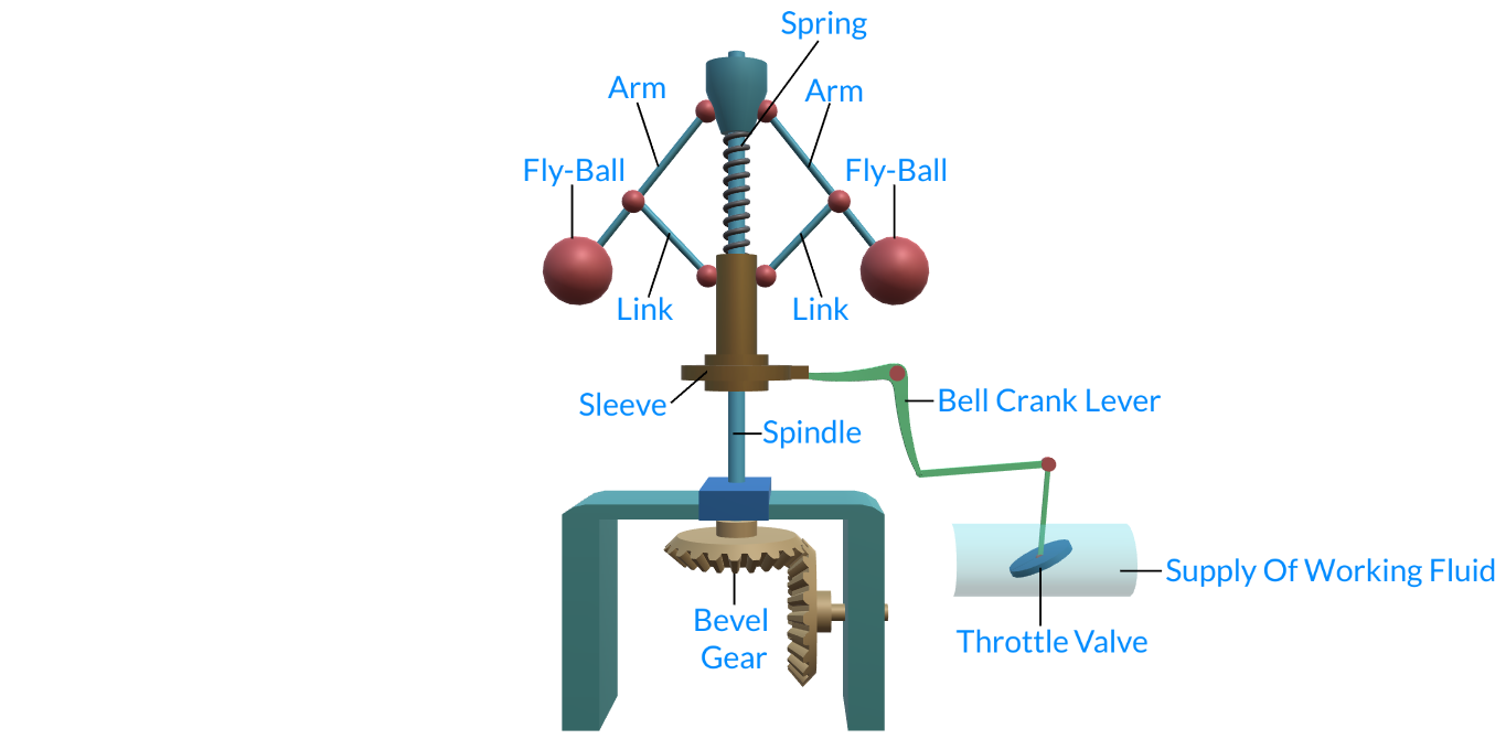
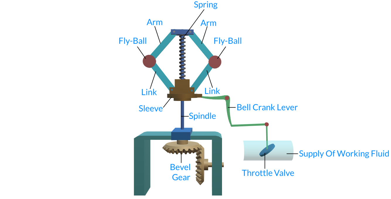
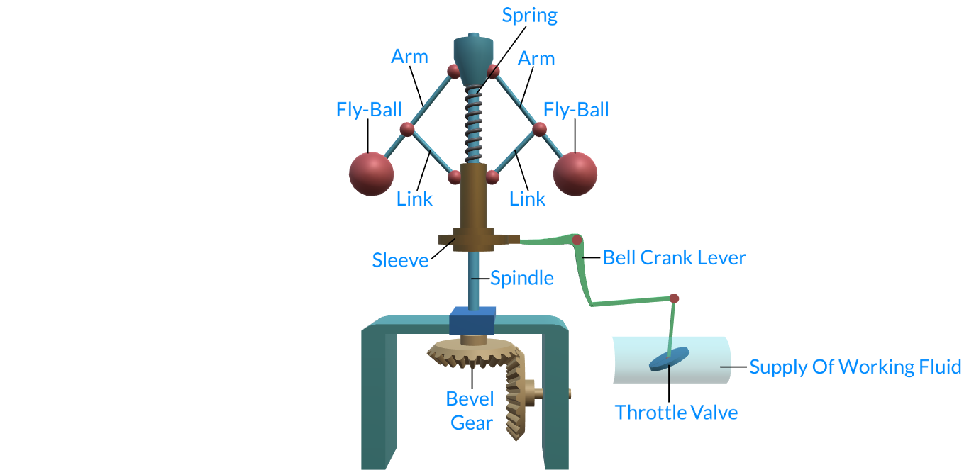
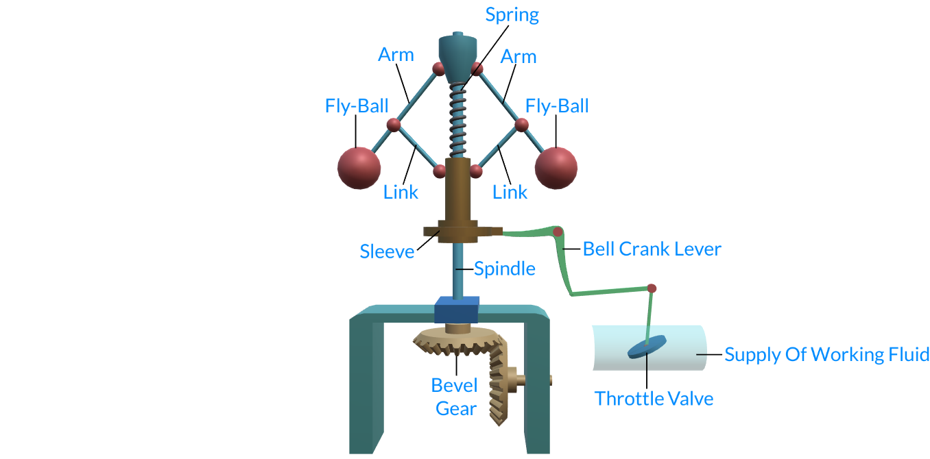
1.2 Governor Components
All governors have five fundamental components:
a)A way to set the desired speed- Setting the “desired speed” of a governor is necessary to efficiently control prime movers. Ina mechanical governor these are normally done by what is called as Speeder Springs the more force applied to this spring, the higher the desired speed setting is.
b) A way to sense actual speed - The governor must receive a force that is proportional to the speed of a prime mover. In mechanical governors, it is done by the centrifugal force of flyweights being rotated from a drive system that is connected to the prime mover, and is directly related to the speed of the prime mover.
c) A way to compare the actual speed to the desired speed - The force of the “desired speed setting” and the force of the “actual speed” are compared or “summed” together. “Desired speed setting” is a force in one direction and “actual speed” is a force in the opposite direction. When these opposing forces are the same value, their sum will be zero and at that point the governor is controlling actual speed at the point of the desired speed setting. If the “desired speed setting” force is stronger than the “actual speed” force, the governor will increase fuel. If the “actual speed” force is stronger than the “desired speed setting” force, the governor will decrease fuel. As fuel is increased or decreased, these forces will change until they balance or “sum to zero.” In mechanical governors, these forces are summed at the “thrust bearing”.
d) A way for the governor to change the fuel to the prime mover - The mechanical governor normally has a rotational or linear output shaft that is connected to the prime mover‘s fuel system. When the governor needs to make a fuel correction to maintain speed (or load), the output shaft moves in the proper direction to correct the final fuel setting.
e) A way to stabilize the engine after a fuel change has been made - Stabilization is accomplished through a variety of ways, but all of them use a “feedback” system to apply a force to the “thrust bearing” or “summing point.” This “feedback” is normally in the form of either droop or compensation, or in a combination of both. Droop or compensation is usually related to the amount the output shaft is told to move.
|
|
1.3 Development of the Modern Governor System
The first modern governors were applied to controlling the speed and load of water wheels (which were used to power many of the early factories during the “Industrial Revolution”. Early governors also controlled steam turbines. The development of gasoline and diesel internal combustion engines required faster and more complex governors. Electrical power generation created a much greater need for more precise governor control of speed and load. Hydro-mechanical governors became ever more complex to meet growing needs for precise control. Since the 1970s, electronic controls have significantly improved and expanded the capabilities of governing systems, controlling not only speed and load, but also electrical loads, exhaust emissions, and many other parameters.
Here in this course we will limit our study to the types of governors mentioned in the next topic.
|
|
1.4 Types of Governors:
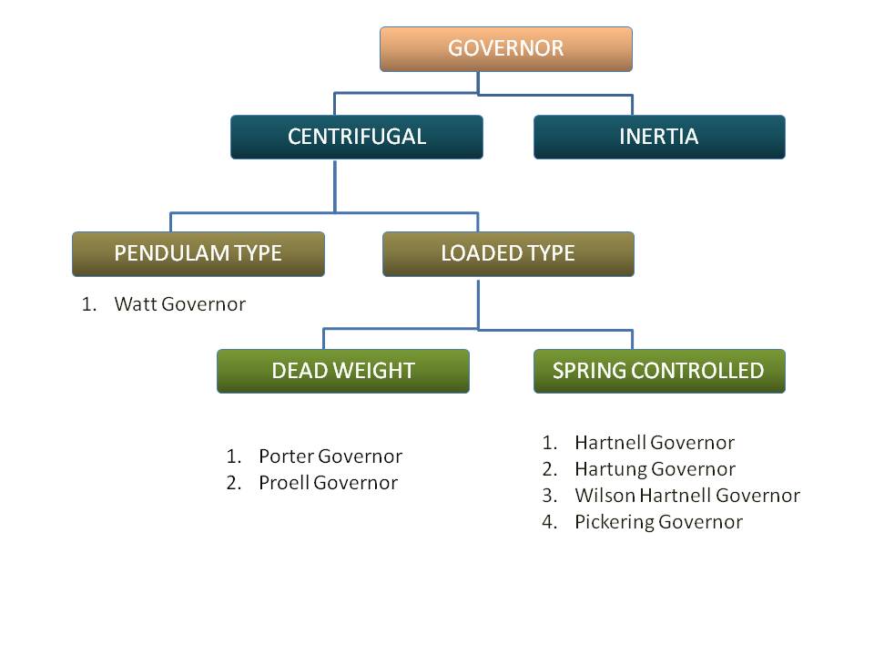
Types of Governors (Fig.- 5.1)
|
|
1.5 Terms used in Governors:
The following terms are used in Governors
a) Height of Governor: It is the vertical distance from the center of the ball to a point on the spindle axis where the axes of arms intersect. It is denoted by h.
b) Radius of rotation: It is the horizontal distance between center of the ball and the axis of rotation. It is denoted by r.
c) Equilibrium speed: It is the speed at which the governor ball, arms, links, etc. are in complete equilibrium and there is no upward or downward movement of the sleeve.
d) Sleeve Lift: It is the vertical distance travelled by the sleeve due to the change in the equilibrium speed from minimum to maximum.

Governors Terms Used
|
|
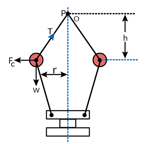
1.6 Watt Governor:
The simplest form of a centrifugal governor is a Watt governor, as shown in figure.
Watt Governors
It is basically a conical pendulum with links attached to a sleeve of negligible mass.
Let,
m = Mass of the ball in kg.
w = Weight of the ball in Newtons = mg
T = Tension in the arm in Newtons.
ω = Angular velocity of the arm and the ball about the spindle axis in rad/s.
r = Radius of the path of rotation of the ball i.e. horizontal distance from the centre of the ball to the spindle axis in meters.
Fc = Centrifugal force acting on the ball in Newtons = m.ω2.r, and
h = Height of the governor in meters.
It is assumed that the weight of the arms, links and the sleeve are negligible as compared to the weight of the balls. Now, the ball is in equilibrium under the action of
1. The centrifugal force (Fc) acting on the ball.
2. The tension (T) in the arm, and
3. The weight (w) of the ball.
Taking moments about point O, we have
Fc×h=w×r=m.g.r
orm.ω2.r.h=m.g.rorh=gω2−−− (Eqn.-5.1)
When g is expressed in m/s2 and ω in rad/s, then h is in meters. If N is the speed in RPM, then
ω2=2πN60−−− (Eqn.-5.2)
Therefore;h=9.812πN60=895N2meters…(g=9.81m/s2)
We see from the above expression that the height of a governor h, is inversely proportional to N2. Therefore at high speeds, the value of h is small. At such speeds the change in the value of h corresponding to a small change in speed is insufficiently to enable a governor of this type to operate the mechanism to give the necessary change in the fuel supply. This governor may only work satisfactorily at relatively low speeds i.e. from 60 to 80 RPM
|
|
1.7 Porter Governor:
The porter governor is a modification of a Watt’s governor in which central mass is attached to the sleeve. The mass moves up and down the central spindle. This additional downward force increases the speed of revolution required to enable the balls to rise to any predetermined level.
Porter Governor
Consider the forces acting on one-half of the governor as shown in Fig.
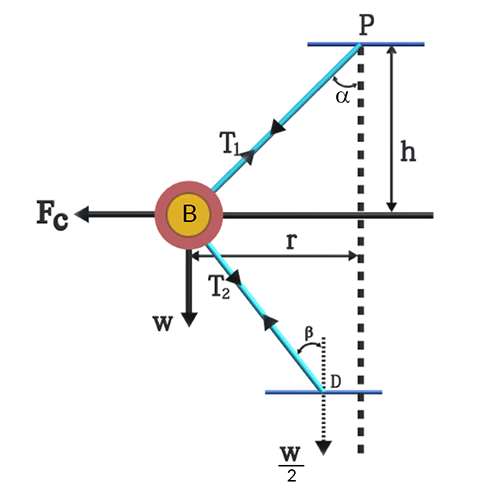
m = Mass of each ball in kg,
w = Weight of each ball in N,
M = Mass of the central load in kg,
W = Weight of the central load in N,
T1 = Tension in upper arm in N.
T2 = Tension in lower arm in N.
r = Radius of rotation in m,
r0 = r - c
h = Height of governor in m,
N = Speed of the balls in rpm.
ω = Angular speed of the balls (2 πN/60) rad/s,
FC = Centrifugal force acting on the ball N,
α= Angle of inclination of the arm (or upper link) to the vertical, and
β = Angle of inclination of the link (or lower link) to the vertical.
Resolving the forces vertically at hinge B
T2cosβ=W2
T2=W(2cosβ)−−− (Eqn.-5.3)
The ball is in equilibrium under the following forces
(i) The weight of ball (w),
(ii) The centrifugal force (FC),
(iii) The tension in the arm (T1), and
(iv) The tension in the link (T2).
Resolving the forces horizontally, we have
Fc=T1sinα+T2sinβ
Fc=T1sinα+W2tanβ
Resolving the forces vertically
T1cosα=T2cosβ+w=W2+w−−− (Eqn.-5.4)
T1sinα=Fc−W2tanβ−−− (Eqn.-5.5)
Dividing Eqn.(5.5) by (5.4), we get and substituting(tanβtanα)=kandtanα=rhwe get
N2=[mg+mg2(1+k)mg]gh(602π)2
N2=[mg+mg±f2(1+k)mg]gh(602π)2−−− (Eqn.-5.6)
The + sign is used when the sleeve moves upwards or the governor speed increases and - sign is used when the sleeve moves downwards or the governor speed decreases.
|
|
1.8 Hartnell Governor :
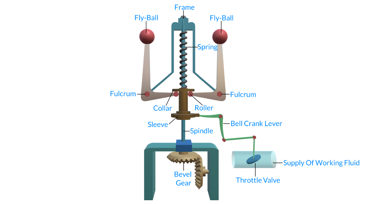
Hartnell Governor
Let,
m = mass of each ball in kg
w= weight of each ball in N
M = mass of each sleeve in kg
W= weight of each sleeve in N
r1 = minimum radius of rotation in m
r2 = maximum radius of rotation in m
w1=speed
w2 = speed
s1= spring force
s2= spring force
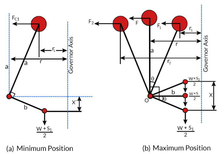
Taking moment about the fulcrum of the bell crank lever and ignoring the effect of the pull of gravity on the governor balls and lever arm
F×a=w+s2×b, or w+s=2Fab−−− (Eqn.-5.7)
Neglecting the obliquity effect of the arm and the moment due to weight of the ball then,
for minimum position r = r1 , F =F1
W+S1=2F1ab−−− (Eqn.-5.8)
for maximum position r = r2 , F =F2
W+S2=2F2ab−−− (Eqn.-5.9)
S2−S1=2ab(F2−F1)
∴ stiffness of the spring p=S2−S1x
again, xb=r2−r1a , or x=(r2−r1)ba
p=2(ab)(F2−F1)(r2−r1)(ba)
p=2(F2−F1r2−r1)(ab)2−−− (Eqn.-5.10)
|
|
1.9 Sensitiveness:
it is generally used to compare the performance of two governors . Consider two governors A and B running at the same speed. When the speed increases or decreases by a certain amount. The life of the sleeve of the governor A is greater than the life of the sleeve of the governor B. Then the governor A is said to be more sensitive than the governor B. thus the greater the life of the sleeve corresponding to a given fractional change in speed, the greater is the sensitiveness of the governor.
Sensitiveness of Governor
Sensitiveness is defined as the ratio of the difference between the maximum and minimum equilibrium speeds h the mean equilibrium speed.
N1=maximum equilibrium speed
N2=minimum equilibrium speed
N=mean equilibrium speed=2N1+N2
Sensitiveness of the governor=N2−N1N=2(N2−N1)N2+N1−−− (Eqn.-5.11)
|
|
1.10 Stability :
A governor is said to be stable. When for each speed within the working range, There is only one radius of the governor balls.
Stability of Governor
At which the governor is in equilibrium. For a stable governor if the equilibrium speed increases, the radius of the governor balls must also increase.
|
|
1.11 Isochronism :
A Governor is said to be isochronous when the equilibrium speed is constant.(i.e. range of speed = 0). For all radius of rotation of the balls within the working range. Isochronism is the stage of infinite sensitivity
For Porter Governor N21=ω+W2(1+K)ωgh1×(602π)2−−− (Eqn.-5.13)
N22=ω+W2(1+K)ωgh2×(602π)2−−− (Eqn.-5.14)
For isochronism range of speed is zero
N2−N1=0⇒N1=N2
or h1=h2, which is impossible . Hence a Porter governor cannot be isochronous.
For Hartnell Governor Mg+S1=2F1×ab=2m(2πN160)2r1ab−−− (Eqn.-5.15)
Mg+S2=2F2×ab=2m(2πN260)2r2ab−−− (Eqn.-5.16)
For isochronous N1=N2,Mg+S1Mg+S2=r1r2
|
|
1.12 Hunting:
It is a condition in which the speed of the engine controlled by the governor fluctuates continuously above and below the mean speed .It is caused by a governor which is too sensitive. Thus, if a governor is too sensitive, it may fluctuates continuously, because, when the load on the engine falls, the sleeve rises rapidly to a maximum position. This shuts off the fuel supply to the extent to effect a sudden fall in the speed.
Hunting of Governors
As the speed falls to below the mean value, the sleeve again moves rapidly and falls to a minimum position to increase the fuel supply. The speed subsequently rises and become more than the average with the result that the sleeve again rises to reduce the fuel supply , this process continuous and is known as hunting.
|
|
1.13 Effort of a Governor:
It is the mean force required on the sleeve to raise it or lower it for a given change in speed. At constant speed the governor is in equilibrium and no force is required to be exerted on the sleeve. With the change of speed, the sleeve moves up or down and a force is required to be exerted on the sleeve till a new position of equilibrium is reached for the changed speed. At the new position, the force required is zero. Thus the mean force required to raise the sleeve from one equilibrium position to the other equilibrium position is called the effort of the governor. For convenience in comparing the different types of governors, to define the effort, as that which will be applied for 1% change of speed.
Consider a Porter governor,N2=[w+W2(1+k)m]1h(602π)2
h=[w+W2(1+k)m]1N2(602π)2−−− (Eqn.-5.17)
For the increased speed, (1+c)N and height remaining same more sleeve load will be required.
h=[w+W12(1+k)m]1(1+c)2N2(602π)2−−− (Eqn.-5.18)
equating eqn. (5.17) and (5.18)
W+W12(1+k)=[W+W2(1+k)](1+c)2
W12(1+k)=[W+W2(1+k)](1+c)2−W
W12(1+k)−W2(1+k)=[w+W2(1+k)](1+c)2−1
(W12−W2)(1+k)=[w+W2(1+k)]2cneglectingc2
Q=(W1−W)2=[W+2w(1+k)]cN
Q=[W+w]c−−− (Eqn.-5.19) for k = 1
|
|
1.14 Power of Governor:
Power of a governor is defined as the work done at the sleeve for a given percentage change of speed.
Power, P = Governor effort x displacement of the sleeve
P = Q x X
X = Displacement of the sleeve
X = (1+k) (h – h1)
h=[w+W2(1+k)m]1N2(602π)2−−− (Eqn.-5.20)
h1=[w+W2(1+k)m]1(1+c)2N2(602π)2−−− (Eqn.-5.21)
Dividing, eqn. (5.20) and (5.21)
hh1=(1+c)2or,h1=h(1+c)2
X=(1+k)(h–h(1+c)2)
X=(1+k)h[1+2c+c2−11+2c+c2]=(1+k)h[2c1+2c]
P=QxX
P=[W+2w1+k]c(1+k)h[2c1+2c]
P=[W+2w1+k][2c21+2c]h(1+k)
P=[W(1+k)+2w][2c21+2c]h
P=[4c21+2c][W2(1+k)+w]h
For k =1P=[4c21+2c][W+w]h−−− (Eqn.-5.22)
|
|
1.15 Controlling Force:
When a body rotates in a circular path, there is an inwards radial force or centripetal force acting on it. In case of governor, centrifugal force in a accompanied by an equal and opposite centripetal force acting radically inwards. This inward force acting on the ball is known as controlling force. This force is provided by the mass of the sleeve and ball in porter governor and by the spring in spring controlled governors.
The graph showing the variation of the controlling force as ordinate with the variation of radius of rotation as abscissa is called controlling force curve. This curve enables one to find out the stability and sensitiveness of the governor.
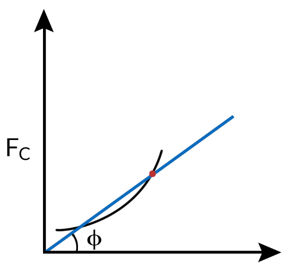
Controlling force (Fig.- 5.12)
Fc=mω2r=m(2πN60)2r
N2=1m(602π)2Fcr
N=602πtanϕm−−−−√−−− (Eqn.-5.23)
between the axis of radius of rotation and a line joining the origin with a specified points on the curve for stable governor .
For a stable governor - Equilibrium speed should increase with the radius of rotation . The controlling force curve should be such that ɸ increase with the radius of rotation .
For sensitive governor - the change in the value of ɸ over the change of the radius of rotation should be as small as possible.
For isochronous governor, the change in the value of ɸ is 0.
i.e. Curve is a straight line passing through the origin.
The angle ɸ may be determined for different values of N and the lines are drawn from the origin.
In order to obtain the speed scale, the controlling force may be calculated for arbitrary chosen values of speed for constant radius of rotation.
|
|
1.16 Controlling Force Diagram For Spring Controlled Governor:
he controlling force curve for a spring controlled governor is approximately a straight line .
For a governor to be stable the controlling force must increase as radius of rotation (r) increases.
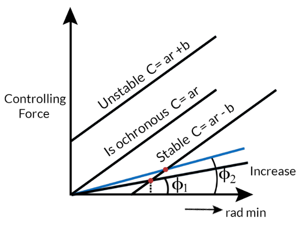
Controlling Force Diagram For Spring Controlled Governor (Fig.- 5.13)
It follows from this that the controlling force curve when produced should intersect Y axis below the x-axis giving the form of the equation C=ar−b
The value of b may be made zero or positive by increasing the initial tension of the spring and the controlling force curve passes through the origin and the governor becomes isochronous.
tanϕ=crConstant for all radius.
If b is greater than zero or positive tanϕ=cr decreases as r increases is the case of unstable governor.
C=ar−b
|
|
1.17 Coefficient of Insensitiveness:
We know that friction always opposes motion and act in downward direction when the sleeve moves up and vice versa. When the speed of rotation decreases, the friction prevents the downward movement of the sleeve and radial inward movement of the balls. On the other hand , when the speed of rotation increases the friction prevents the upward moment of the sleeve and radial outward movement of the balls.
Let,
Fs = Friction force at the sleeve
C = Controlling force on each ball
W= total load on the sleeve.
For increase in speed , the sleeve will move up an load on the sleeve
W1 = W + Fs
For decrease in speed , the load on the sleeve will be
W2=W-Fs
Similarly for increase in speed, controlling force become
C1=C + FB
For decrease in speed
C2 = C - FB
When the radius of rotation is r, the speed of rotation may vary within the limits Nʹ and Nʺ without causing any displacement of the governor sleeve. The governor is said to be insensitive if the speed fluctuates over this range.
Coefficient of Insensitivness =Nʺ−N′N
The relation between Fs and FB may be evaluated in the following
Coefficient of Insensitiveness (Fig.- 5.14)
Coefficient of Insensitiveness (Fig.- 5.15)
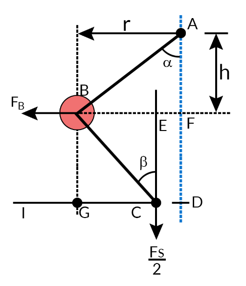
For porter Governor
FB×BG=Fs2×Ic
FB=Fs2×[IG+GCBG]=Fs2[tanα+tanβ]
FB=Fs2×[1+K]rh−−− (Eqn.-5.24)
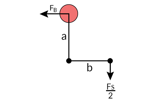
For hartnell Governor (spring controlled)
FB×a=Fs2b
FB=Fs2ba−−− (Eqn.-5.25)
|
|
1.18 Application of Governor:
(i) Engines used in lawn mowers, portable generators and garden tractors are equipped with governor.
(ii) In Aircraft propellers the governor senses shaft RPM and adjusts or controls the angle of the blades to vary the load on the engine.
|