|
1.1 Turning moment diagram and flywheel
|
|
1.2 Turning moment on crankshaft:
Piston effort (Fp) is termed as the net effective driving force applied on the piston and acts along the line of stroke. In reciprocating engines, the reciprocating masses accelerate during the first half of the stroke and inertia force tends to resist the same. The net force on the piston is decreased. During the latter half of the stroke, the reciprocating masses decelerate and the inertia force opposes this deceleration or acts in the direction of the applied gas pressure and increase the effective force on the piston.
Let
Fp = Piston effort.
Q= force in the connecting rod.
r= Radius of the crank.
L = Length of the connecting rod.
n = Ratio of the connecting rod length and radius of the crank = Lr.
θ = Angle turned by the crank from Inner Dead center (IDC).
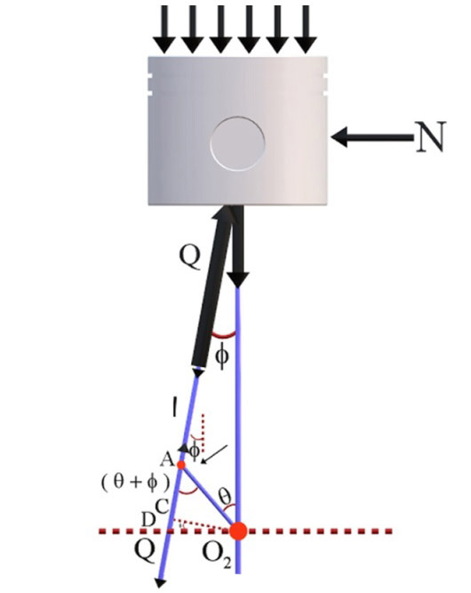
Turning Moment On Crank Shaft (Fig.- 7.1)
From FBD,
Qcosɸ=Fpor,Q=Fpcosɸ
Qsinɸ=N
Let Ft = crank effort
Turning moment on the crankshaft
T=FT×r
=Q×rcos[90–(θ+ɸ)] => =Q×rsin(θ+ɸ) => =Fp×rsin(θ+ɸ)cosɸ,
Also Lsinϕ=rsinθ+>sinϕ=sinθn, since n=Lr,
Thus Cosϕ=1−sin2ϕ−−−−−−−−√=1−sin2θn−−−−−−−√, and tanϕ=sinϕcosϕ=sinθn×nn2−sin2θ√=sinθn,
since n2>>sin2θ,
Therefore T.M=Fp.r[sinθ+cosθ.tanϕ]=Fp.r[sinθ+cosθ.sinθn],
Hence T.M=Fp.r[sinθ+2cosθ.sinθ2n]=Fp.r[sinθ+sin2θ2n]
|
|
1.3 Turning moment diagram:
Turning moment diagram also known as crank effort diagram is the graphical representation of the turning moment for various position of the crank. It is plotted on Cartesian co-ordinates in which the turning moment is taken as the ordinate and crank angle as abscissa.
The turning moment on the crankshaft for different types of engines are given below:
T.M=Fp.r[sinθ+sin2θ2n]
|
|
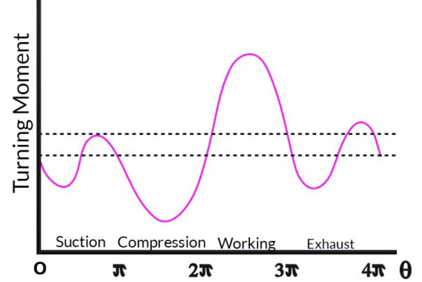
1.3.1 Single cylinder four stroke engine:
In case of four stroke I. C. Engine, the diagram repeats itself after every two revolution. During the suction stroke, the pressure inside the cylinder is less than the atmospheric pressure. As a result a negative loop is formed. A higher negative loop is also obtained during compression stroke since the work is done on the gas. During the expansion or working stroke, the fuel burns and the gases expand; therefore a large positive loop is obtained. The work is done by the gases during this stroke. Again a negative loop is formed during exhaust stroke since the work is done on the gases
Single_Cylinder_Engine
|
|
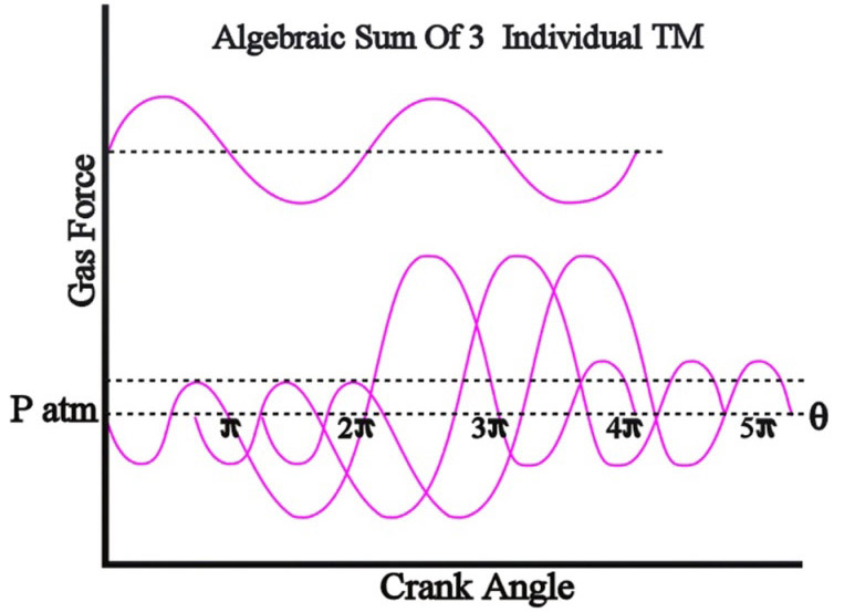
1.3.2 Multi Cylinder Engine:
In case of multi cylinder engine there will be more expansion strokes. As a result there will be lesser variation in turning moment compared to single cylinder engine and consequently there is expected to be less variation in speed. Thus the variation in the TM reduces with the increase in the number of cylinders. In the figure the turning moment diagram is the sum of the turning moment diagram for the three cylinders. The first cylinder is high pressure cylinder, second is intermediate and third is low pressure cylinder. The cranks in case of three cylinders are usually places at 120 degree to each other.
3_Cylinder_Engine
|
|
1.3.3 Single Cylinder Double Acting Stem Engine
Single Cylinder Double Acting Stem Engine (Fig.- 7.4)
|
|
1.4 Fluctuation of energy and speed
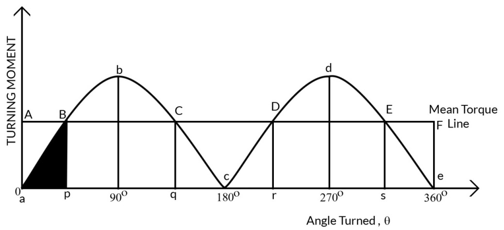
The curve abc represent the turning moment diagram for outstroke and cde represents the inner stroke.
The area of the turning moment diagram represents the work done per revolution. In actual practice, the engine is assumed to work against the mean resistive torque represented by a figure f. The mean resisting torque line AF cuts the turning moment diagram at BCDE. When the crank moves from a to p, the work done by the engine is equal to area aBp whereas the energy required is represented by the area aABp. So, the engine has done less work than the requirement. This amount of energy is taken from the flywheel and the speed of the flywheel decreases. Now the crank moves from p to q. The work done by the engine is equal to the area pBbCq whereas the requirement of the energy is represented by the area pBCq. Therefore, the engine has done more work than requirement. This excess work is stored in the flywheel and hence the speed of the flywheel increases while the crank moves from p to q. Similarly, when the crank moves from q to r, more work is taken from the engine than developed. This loss of work is represented by the area CcD. To supply this loss, the flywheel gives up some of its energy and thus the speed decreases. As the crank moves from rto s excess energy is again developed given by the area DdE and the speed again increases.
As the crank moves from s to e again there is a loss of work and the speed decreases. The variation of energy above and below the mean resisting torque line is called the fluctuation of energy. Area BbC, CcD, DdE etc. represent fluctuation of energy.
The difference between the maximum and the minimum energy is known as maximum fluctuation of energy and is represented by emax.
emax = Maximum energy (E1) - Minimum energy (E2)
Flywheel stores energy and will have maximum value at maximum speed and minimum value at minimum speed. Engine has maximum speed either at q or at s and minimum speed either at p or at r. This is due to the fact that the flywheel absorbs energy while the crank moves from p to q and r to s. On the other hand, the flywheel gives out some of its energy when the crank moves from a to p and q to r.
|
|
1.4.1 Co-efficient of Fluctuation of Energy:
It is defined as the ratio of the maximum fluctuation of energy to the work done per cycle
Ce=Maximumfluctuationofenergy workdonepercycle
Calculation of work done per cycle:
Work done per cycle = Tmean×θ
θ = angle turned in one cycle
= 2π for two stroke I. C. Engine
= 4π for four stroke I. C. Engine
|
|
1.4.2 Co-efficient of Fluctuation of Speed:
The difference between maximum and minimum speed is known as maximum fluctuation of speed. The ratio of the maximum fluctuation of speed to the mean speed is known as co-efficient of fluctuation of speed.
Let,
N1 = Maximum speed in rpm, w1 = Maximum angular speed
N2 = Minimum speed in rpm, w2 = Minimum angular speed
N = Mean speed in rpm w = Mean angular speed
q=(N1−N2)N,N=(N1+N2)2
q=2(N1−N2)(N1+N2)=2(w1−w2)(w1+w2) - - - - - - - - - - - - (Eqn.-7.3)
|
|
1.4.3 Maximum Fluctuation of Energy for Multi-Cylinder Engine:
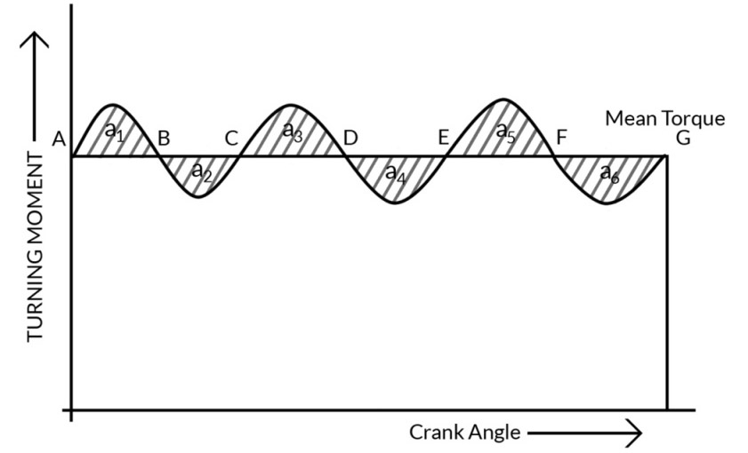
Maximum Fluctuation of Energy for Multi-Cylinder Engine (Fig.- 7.5)
These areas represent some energy which is either added or subtracted from the energy of moving part of engine. Let,
Energy at A=E
Energy at B=E+a1
Energy at C=E+a1-a2
Energy at D=E+a1-a2+a3
Energy at E=E+a1-a2+a3-a4
Energy at F=E+a1-a2+a3-a4+a5
Energy at G=E+(a1+a3+a5)-(a2+a4+a6)
Maximum fluctuation of energy=Maximum energy-Minimum energy.
|
|
1.5 Classification of Flywheel:
|
|
1.5.1 Flywheel Design
Flywheel is used in machines serves as a reservoir which stores energy during the period when the supply of energy is more than requirement and releases it during the period when the requirement energy is more than the supply. During the period when it absorbs energy its speed increases and during the period when it releases energy its speed decreases. Hence, a flywheel does not maintain a constant speed, it simply reduces the fluctuation of speed. Thus, a flywheel controls the speed variation caused by the fluctuation of the engine turning moment during each cycle of operation.
Based on the mode of operation, there are two kinds of flywheel
(A) Disc type - suited for smaller size engine / machine.
(B) Arm type – suited for larger size engine / machine.
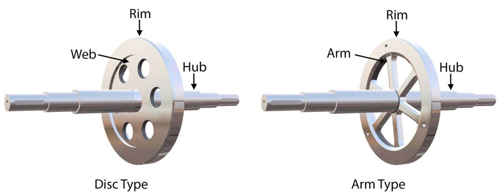
Types
Energy stored in a flywheel:
Let, E1 = Maximum energy
E2 = Minimum energy
I = mass moment of inertia of the flywheel= mk2
emax = E1- E2
12[Iω21−Iω22]=I2[ω21−ω22]
=I2(ω1+ω2)(ω1−ω2)
= 1/2I [w1+w2][w1-w2]
= Iw2 (w1-w2)/w
= 2*Iw2q/2
=2Eq
Therefore;emax=Iw2qÀÀÀ (Eqn.-7.4)
|
|
1.6 Function of flywheel:
The main function of a flywheel is to smoothen out variations in the speed of a shaft caused by torque fluctuations. If the source of the driving torque or load torque is fluctuating in nature, then a flywheel is usually called for. Many machines have load patterns that cause the torque time function to vary over the cycle. Internal combustion engines with one or two cylinders are a typical example. Piston compressors, punch presses, rock crushers etc. are the other systems that have flywheel. Flywheel absorbs mechanical energy by increasing its angular velocity and delivers the stored energy by decreasing its velocity.
|
|
1.7 Dimension Of The Flywheel Rim:
Let,
ω = angular velocity of the flywheel, rad/sec
A = cross sectional area of the rim, m2
R = mean radius of the rim, m
t = thickness of the rim, m
ρ = density of the material, kg/m3
σ = tensile stress or hoop stress due to the centrifugal force, N/m2
v = linear velocity at the mean radius, m/sec
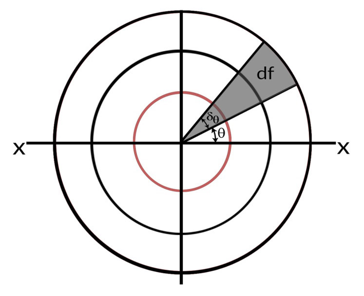
Dimension Of The Flywheel Rim (Fig.- 7.7)
Consider small element of the rim shaded in the figure. Let it subtends an angle δθ at the center of the flywheel.
Volume of the small element,dV=AR.δθ
Mass of the small element, \(dm = \rho AR .\delta \theta\)
Centrifugal force of the element acting radially outwards, dF=dmω2R=ρAR2ω2δθ[Centrifugalforce,C=mω2r]
Vertical component of dF=dFsinθ=ρAR2ω2sinθ.δθ
Total vertical upward force tends to burst the rim across the diameter XX.
=∫π0dFsinθ=∫π0AR2ω2sinθδθ=2ρAR2ω2
This vertical upward force will produce hoop stress.
Total resisting force ==2σA
Equating, 2σA=2ρAR2ω2
σ=ρ(Rω)2=ρv2
|
|
1.8 Applications:
|
|
1.8.1 IC Engine
|
|
1.8.2 Sheet Metal Press
|
|
1.9 Flywheel in punching press:
Generally punching presses are driven by motors or by IC Engines. The energy supplied by motor is constant. When the load is applied on the press, the speed decreases and when the load decreases, the speed increases. Drop in speed will be large when the load is suddenly applied.
Let
d = diameter of the hole
t = thickness of the plate
Tu = ultimate shear stress
Maximum shear force, Fs= Area sheared X ultimate shear stress = πdtTu
as the hole is punched the shear force decreases uniformly from maximum value to zero.
Energy required for punching hole per revolution,
E1=FS2t
The energy supplied by the motor to the crankshaft during actual punching operation.
E2=E1(θ2−θ1)2π
Balance energy required for punching = Maximum fluctuation of energy which is supplied by the flywheel.
ΔE=E1−E2=E1[1−θ2−θ12π]
Sinceθ2−θ12π=t2s=t4rwhere,s=stroke=2r
ΔE=E1[1−t4r]where,E1=Fs2t
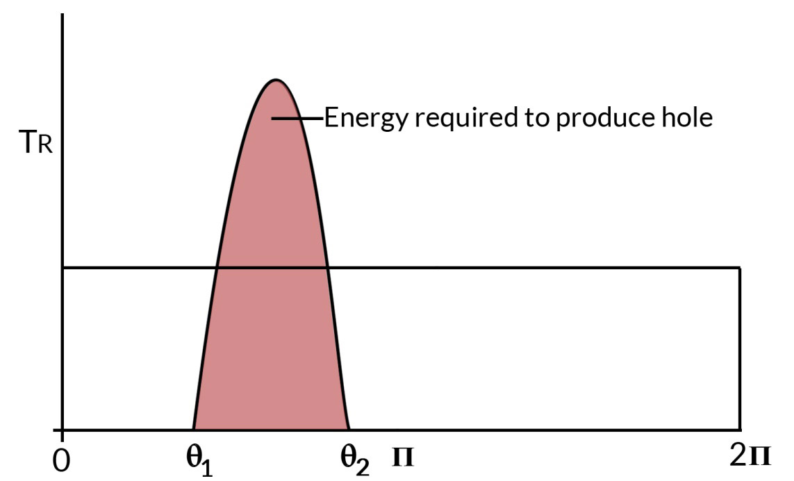
Flywheel In Punching Press (Fig.- 7.8)
|
|
1.10 Kinematic Energy Recovery System (KERS):
While driving a vehicle, the speed of the vehicle is not always constant. Brakes are applied as and when required. While applying brakes, the K. E. of the vehicle is reduced. The K. E is converted into non-recoverable energy in the form of heat or sound at the brake shoes and is dissipated into the surroundings. KERS is an efficient method of recovering this energy, which would otherwise be wasted. The mechanical KERS use high speed flywheel kept inside a vacuum seated container as the energy storage device. KERS are used effectively in Formula 1 racing car. The energy lost by the car in the curves is stored and can be used in straight track.
|