|
1.1 Belts
Belts are power transmission components. The function of a belt drive is to transfer rotation from one shaft to another, eitherto transfer power, or convey product. The different types of belts available for each purpose shows how adaptable belts are to any industry.
Advantages and disadvantages of Belt drive
Advantages:
- No lubrication is required.
- Dampens shock loads.
- Quieter than chain drives.
- Low maintenance.
- Low wear on pulleys so they have long working life.
- Belts are not expensive to replace.
Disadvantages:
- Belts can’t be repaired and length can’t be adjusted.
- Extreme environmental conditions such as extreme temperatures, high moistureand exposure to chemicals can damage the belts.
|
|
1.2 Types of Belts
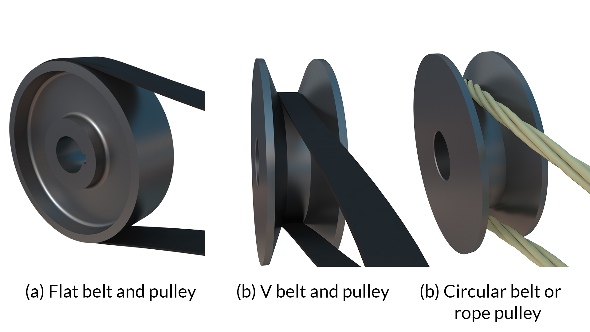
The flat belt is rectangular in cross-section. All flat belts have a natural tendency to move laterally. Therefore a flat or straight pulley is not recommended, as the belt would walk off the pulley. To keep the belt in the centre of the pulley it must have a crown. The V-belt is trapezoidal in section. It utilizes the force of friction between the inclined sides of the belt and pulley. They are preferred when distance is comparative shorter. Several V-belts can also be used together if power transmitted is more.
The circular belt or rope is circular in cross section. Several ropes also can be used together to transmit more power.
|
|
1.3 Belt Drives
- open belt drive, and
- cross belt drive.
|
|
1.3.1 Open Belt Drive
Open belt drive is used when drive and driven pulley has to rotate in the same direction. It is desirable to keep the tight side of the belt on the lower side and slack side at the top to increase the angle of contact on the pulleys.
Open Belt Drive (Fig.- 4.1)
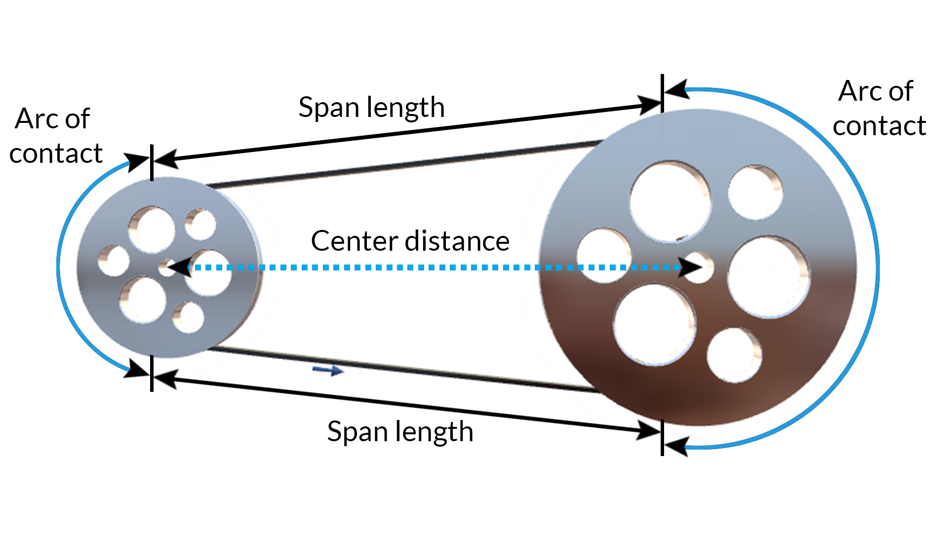
The standard terms used in V belt and timing belt drives:
- Driverdrive pulley or motor pulley
- Drivendriven pulley or final pulley
- Span length where the belt leaves one pulley and then touches the other pulley.
- Centre distance the distance between the centre of the pulleys, used for determining the belt length with a calculation
- Arc of Contact the angle of wrap around each pulley – the bigger the arc of contact is the more power can be transmitted
|
|
1.3.2 Open Belt Drive
In cross belt drive, the pulleys rotate in the opposite direction. The angle of contact of belt on both the pulleys is equal. In this kind of drive the belt has to bend in two different planes. As a result of this, belt wears very fast and therefore, this type of drive is not preferred for power transmission. This can be used for transmission of speed at low power.
|
|
1.4 Length of the Belt
The length of the belt is determined by taking a measuring tape and following the path of the belt around all of the pulleys, or through computer aided design (CAD) techniques.
|
|
1.4.1 Open Belt Drive
The open belt drive is shown in the figure. Let O1 and O2 be the pulley centres and AB and CD be the common tangents on the circles representing the two pulleys. The total length of the belt ‘L’ is given by
L = Belt length
C = Centre of pulley shaft to centre of pulley shaft distance
D = pitch diameter of large pulley
d = pitch diameter of small pulley
β be the angle subtended by the tengents AB and CD with O1O2
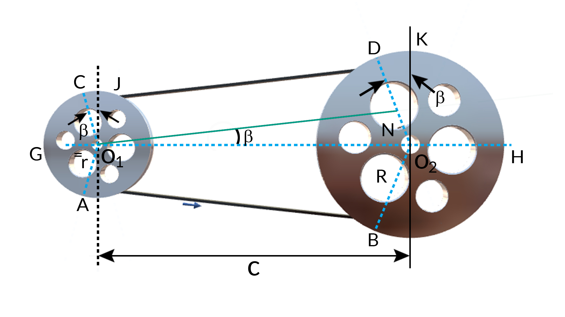
L = AB + Arc BHD + DC + Arc CGA, or
L=2C+Π2(D+d)+(D−d)24C
|
|
1.4.2 Cross belt drive
The crossed belt drive is shown in the figure. Let O1 and O2 be the pulley centres and AB and CD be the common tangents on the circles representing the two pulleys. The total length of the belt ‘L’ is given by
L = Belt length
C = centre of pulley shaft to centre of pulley shaft distance
D = pitch diameter of large pulley
d = pitch diameter of small pulley
β = angle subtended by the tangents AB and CD with O1O2
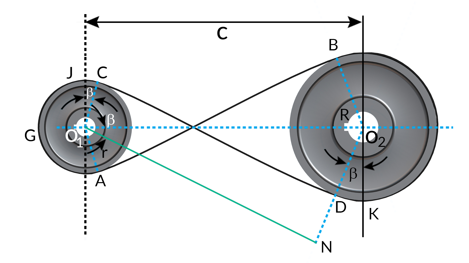
Length of the belt is
L = Arc AGC+AB+ArcBKD+CD, or
L=2C+Π2(D+d)+(D+d)2C
|
|
1.5 Belt Velocity Ratio
Since power transmitted by a belt drive is due to the friction, belt drive is subjected to slip and creep. Let d1 and d2 be the diameters of driving and driven pulleys, respectively. N1 and N2 be the corresponding speeds of driving and driven pulleys, respectively.
The velocity of the belt passing over the driver.
V1=πd1N160
If there is no slip between the belt and the pulley
V1=V2=πd2N260, thus πd1N160=πd2N260 or N1N2=d2d1
If thickness of belt is 't', and it is not negligible in comparision to the diameter,
N1N2=d2+td1+t
Let there be total percentage slip 'S' in the belt drive which can be taken into account as follows:
V2=V1(1−S100) or πd1N160=πd2N260(1−S100) and if the thickness of the belt is to be considered then,
N1N2=d2+td1+t1(1−S100), or N2N1=(d1+t)(d2+t)(1−S100)
The belt moves from the tight side to the slack side and vice-versa, there is some loss of power because the length of belt continuously extends on tight side and contracts on loose side. Thus, there is relative motion between the belt and pulley due to body slip. This is known as creep.
|
|
1.6 Ratio of belt tension
A belt is able to transmit power from one shaft to another throguh the friction between the belt and pulley. Due to this riction the belt becomes tight on one side and slack on the other side. Let us determine the tensions on the belt tight and slack side
|
|
1.6.1 Flat belt
As in the figure below
Let,
Tension on tight side – T1
Tension on slack side - T2
Angle of Lap – θ
Friction coefficient between belt and pulley - µ
Consider and infinitesimal length of the belt PQ which subtends an angle δθ at the centre fo the pulley.
Let 'R' be the reaction between the element and the pulley. Let 'T' be tension on the slack side fo the element. i.e. at point 'P' and let '(T + δT)' be the tension on the right side of element.
The tension T and (T + δT) shall be acting tangential to the pulley and there by normal to radii OP and OQ. The fraction force shall be equal to 'µR'and its action will be to prevent slipping of the belt. The friction force will act tengentially to the pulley at the point S.
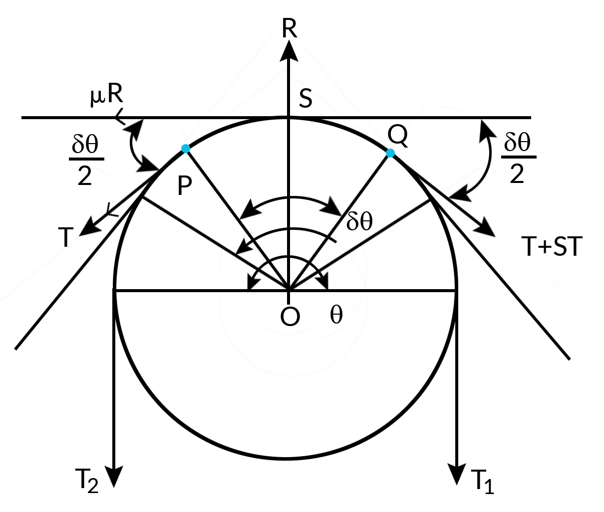
Considering equilibrium of the element at S and equating to zero.
Resolving all the forces in the tangential direction
μR+Tcosδθ2−(T+δt)cosδθ2=0 => μR=δtcosδθ2
Resolving all the forces in the direction at S and equating it to zero
R−Tsinδθ2−(T+δt)sinδθ2=0 or R=(2T+δt)sinδθ2
since δθ is very small, taking limits
cosδθ2=1andsinδθ2=δθ2
therefore, R=(2T+δt)δθ2orR=Tδθ+δθ.δt2
Neglecting the product of two infinitesimal quantities δθ.δt2, we get R=Tδθ
Substituting the value of R and cosδθ2 in μR=δtcosδθ2
we get, μTδθ=δt=>δtT=μδθ
Taking limit on both sides as δt−>0dtT=μdθ
Integrating between limits, it becomes
∫T1T2dtT=∫θ0μdθ , or lnT1T2=μθ, or T1T2=eμθ
|
|
1.6.2 V-belt or Rope
V-belt or rope makes contact on the two sides of the groove as shown
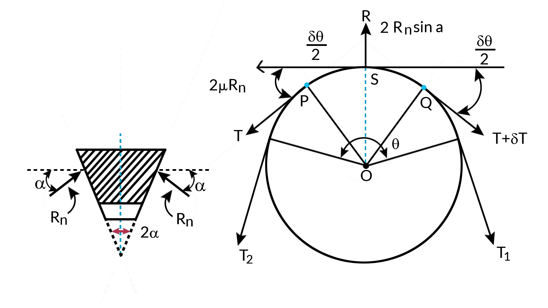
Let the reaction be 'Rn' on each of the two sides of the groove. the resultant reaction will be 2Rnsinα at point S.
Resolving all the forces tangentially we get
2μRn+Tcosδθ2−(T+δt)cosδθ2=0 or 2μRn=δtcosδθ2
Resolving all the forces radially, we get 2RnSinα=TSinδθ2+(T+δt)sinδθ2, or
2RnSinα=(2T+δt)sinδθ2
since δθ is very smallsinδθ2=δθ2
∴ 2Rnsinα=Tδθ+δt.δθ
Neglecting the product of two infinitesimal quantities
2Rnsinα=Tδθ , or Rn=Tδθ2sinα
Substituting the value of Rn and using the approximitation cosδθ2=1, in 2μRn=δtcosδθ2
We get
2μTδθ2sinα=δt=>δtT=μsinαδθ
Taking the limits and integrating between limits, we get
∫T1T2dTT=∫θ0μsinαdθ => ln(T1T2)=μsinαθ, which can be further written as T1T2=eμsinαθ
|
|
1.7 Power Transmitted by belt drive
The power transmitted by belt depends on tension on the two sides and the belt speed.
Let,
- T1 be the tension on the right side 'N'.
- T2 be the tension on the slack side in 'N' and,
- V be the speed of the belt in m/sec.
Then power Transmitted by the belt is given by
Power, P=(T1−T2)Vwatt, or P=T1(1−T2T1)watt, but when the belt is at the point of slipping we have , T1T2=eμθ
then Power, P=T1(1−e−μθ)watts
The maximum tension T1 depends on the capacity of the belt to withstand force. If allowable stress in the belt is ' δt' in 'Pa', i.e. N/m2, then
T1=σt.t.bN
Where t is the thickness of the belt in meters and b is width of the belt also in meters. This equation can also be used to determine 'b' for given power and speed.
|
|
1.8 Tension due to Centrifugal Forces
The belt has mass and it rotates along with the pulley then it is subjected to centrifugal forces. If we assume that no power is being transmitted and pulleys are rotating, the centrifugal force will tend to pull the belt as shown and, thereby, a tension in the belt is called centrifugal tension will be introduced.
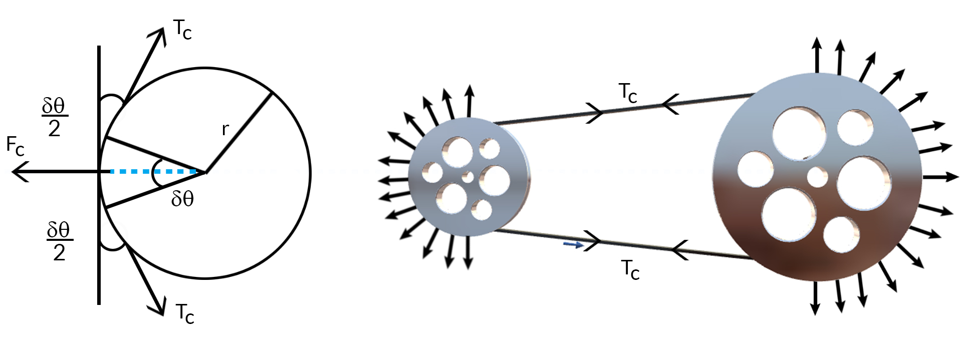
Let 'Tc' be the centrifugal tension due to centrifugal force.
Let us consider a samll element which subtends an angle δθ at the center of the pulley.
Let 'm' be the mass of the belt per unit length of the belt in 'kg/m'.
The centrifugal force 'Fc' on the element will be given by
Fc=(rδθm)V2r
where V is the speed of the belt in m/sec. and r is the radius of pulley in 'm'.
Resolving the forces on the element normal to the tangent
Fc−2Tcsinδθ2=0
since δθ is very small
∴ sinδθ2=δθ2
or,
Fc−2Tcδθ2=0
or,
Fc=Tcδθ, Substituting for FC in Fc=(rδθm)V2r, we get
Tcδθ=(r.m.δθ)V2r=>Tc=mV2
Therefore consideing the effect of the centrifugal tension, the belt tension on the right side when power is transmitted is given by
Tension of right side Tt=T1+Tc and the tension on the slack side Ts=T2+Tc.
The centrifugal tension has an effect on the power transmitted because maximum tension can be only Tt which is
Tt=σt.t.b, therefore T1=σt.t.b−mV2
|
|
1.9 Initial Tension
When belt is mounted on the pulley some amount of initial tension say 'T0' is provided in the belt, otherwise power transmission is not possible because of loose belt can not sustain difference in the tension and no power can be transmitted. When the drive is stationary the total tension on both sides will be '2T0'. When belt drive is transmitting power the total tension on both sides will be 'T1 + T2', where T1 is tension on right side and T2 is tension on the slack side.
If the effect of centrifugal tension is neglected .
2T0=T1+T2 or, T0=T1+T22
If the effect of centrifugal tension is considered, then
2T0=Tt+Ts=T1+T2+2Tc or, T0=T1+T22+Tc
|
|
1.10 Maximum Power Transmitted
The power transmitted depends on the tension 'T1', angle of lap θ, coefficient of friction 'μ' and the belt speed 'V'. For a driven belt drive, the maximum tension (Tt), angle of lap and coefficient of friction shall remain constant provided that
- the tension on right side, i.e. maximum tension should be equal to the maximum permissible value for the belt,and
- the belt should be at the point of slipping
Therefore, Power P=T1(1−e−μθ)V
since, T1=Tt+Tc
or,
P=(Tt−Tc)(1−e−μθ)V
or,
P=(Tt−mV2)(1−e−μθ)V, for mximum power transmitted, we differentiate the expression and equate to 0. Hence
dPdV=(Tt−3mV2)(1−e−μθ)=0 ,Thus
Tt−3Tc=oorTc=Tt3, also Tc=mV2,
therefore V=Tt3m−−−√
At the belt speed given by the above equation. the power transmited by the belt drive shall be maximum.
|